
In the Marine Industry, the impact of equipment failure is a uniquely specialized event. Ships at sea, unlike shore-bound physical plants, do not have the luxury of local maintenance and repair operations onboard and must instead carry their own troubleshooting solutions with them. Because of this, what might have been perceived as a small or temporary risk on shore may be perceived as a much more serious concern in the open water.
1. CRITICALITY/RISK
Depending on the route, mission and the cargo being transported, the risk created by individual component downtime can be extremely varied. It may be minimal – for example, the case of a temporary disruption of cabin comfort is an operationally negligible event, whereas the loss of temperature control in a container carrying hazardous or spoilable content can be catastrophic. Being that redundant systems can help mitigate risk, it is important to understand the relative criticality of uptime. Risks, therefore, can be categorized in regards to the Consequence of Failure (CoF):
The impact of failure of each component in a Marine automation system can therefore be assessed to determine criticality of uptime of that component. For example, in vessels described by the International Maritime Organization (IMO) as either Class 2 (which must have redundancy adequate to prevent a single point of failure from causing the system to fail) and Class 3 (which because of hazardous cargo must be able to withstand fire or flood in an individual compartment without system failure) redundant dynamic positioning systems are required to assure the safe transport of goods. The associated level of risk therein will help determine the selection of appropriate methodologies for system, communication and device redundancy.
2. MAXIMUM TOLERABLE DOWNTIME (MTD)
Based on this perceived criticality of uptime for individual components, a maximum tolerable downtime (or permissible time of failure) will need to be determined to assure that each device is operating as expected. Traditionally, these MTD time frames have been classified as being: cold, warm or hot and have corresponding systemic redundancies associated with them.
Cold Redundancy implies a non-critical process that can withstand a greater amount of downtime than can other failure responses. A very simple example of cold redundancy in our non-industrial world may be a light bulb burning out and being replaced with a spare by human intervention. Another basic example may be a CPU being rebooted without concern for overt risk. Frequently in the Maritime industry, these instances may take the form of discrete Alarms and Monitoring. After reaching a predetermined trigger point – perhaps low oil pressure in a gearbox, for example – or an impeded raw water flow through a seacock fitting – an alarm is triggered generating a troubleshooting/maintenance call.
Warm Redundancy is more mission-critical in nature. In shipboard automation systems, these would require more immediate, automated interventions to protect safety, equipment and cargo. Typically these would encompass more risk-sensitive forms of alarms and monitoring than is found in Cold Redundancy systems. Generally, a system of this type would utilize two PLCs communicating with each other over a redundant Ethernet network. One would serve as the Master PLC with the other serving as a standby unit. If a failover situation arises from an incident such as power loss, network or device failure or even from a catastrophic event such as destruction from a physical impact, the system would transfer control to the secondary PLC at the speed of the network topology – typically between 100 – 500 ms.
Hot Redundancy is required in cases as described before regarding Class 3 vessels carrying hazardous or time-sensitive cargo. In these mission-critical cases, the failover needs to be near instantaneous. Redundancy for these instances may need to be achieved via three or more PLCs running simultaneously using a voting logic to determine, i.e., ‘vote’ on which PLC serves as the master at any given moment. Obviously this method of redundancy while being the quickest and most responsive would also be considerably more expensive than cold or warm solutions.
In all cases, the Maximum Tolerable Downtime allowable for the predetermined risk that could be absorbed would determine which methodology is best suited for individual system and component requirements.
3. NETWORKING
With the level of acceptable risk and the type of system redundancy determined in conjunction with time considerations, network considerations of the automation system become the next decision-sets to be addressed. While traditional fieldbus systems remain prevalent in industry, Ethernet-based networks have become ubiquitous offering flexibility and scalability for a variety of applications.
EMI / Transmission media
One of the factors that can decidedly hinder smooth network performance at sea is electromagnetic interference or EMI. On board a ship, EMI can be generated from a number of common sources including starters, alternators, motors, engines, generators, inverters and even from radar and other positioning or communication devices. This concern greatly impacts the selection of network transmission media. While Ethernet cabling comes in a variety of categories and flavors, shielded twisted pair or fiber optic options when implemented under best practices can provide a clean and continuous signal, i.e., when grounded/drained through a properly connected shield connector or busbar.
Topology
While some vessels may require complicated – and expensive – mesh networks using a triple PLC voting methodology to assure extremely high-speed failover, typically for the marine industry either Dual LAN Redundancy or Token Ring Redundancy is more than sufficient.
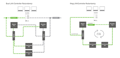
Dual LAN Redundancy
As its name implies, this method of providing redundancy connects two identical local area networks through a single SCADA server. As was discussed regarding Warm Redundancy, dual LAN systems feature master and standby PLCs which communicate with each other to assure that each controller has current knowledge of the prevailing logic of the system. Depending on the number of devices duplicated along each iteration of the LAN, each will also feature corresponding redundant industrial unmanaged switches to reroute network traffic efficiently when failure is detected.
Ring LAN Redundancy
Ring LAN Redundancy utilizes many of the same principles, such as paired master and standby PLCs, as does the Dual LAN Redundancy concept, but it does so in a more cabling-efficient ring arrangement. Both concepts provide device stability and generate similarly rapid, i.e., warm, failover rates of transferring control to the respective standby PLCs; however there are advantages to each. The main difference between the two topologies in practice is that while the Ring Redundant model is fault-tolerant within the Ring itself, it is vulnerable to a single point of failure occurring along the cable that connects the SCADA server to the ring through its one port, whereas the Dual LAN Redundancy concept accesses the SCADA server via two ports and is hence less vulnerable in that regard. The disadvantage of the Dual LAN Redundancy concept is that total network redundancy comes with an increase in complexity and may incur additional costs for cabling and the requisite labor for installation.
Regardless of the slight advantages of one Topology over the other, both are extremely valid methods of helping assure the valuable uptime that we seek through Warm Redundancy.
Switches
The choice of transmission media combined with the topology preference will – in many respects – help inform the decision-making process regarding the selection of industrial managed (for Ring topology) and unmanaged (for Dual LAN topology) Ethernet switches. As the essential means of rerouting network traffic, it is imperative that the switches be rugged, reliable and constantly available. It is also important that they are manufactured for the conditions that will be encountered at sea in terms of vibration, temperature and salt-induced corrosion.
Speed, like most selection criteria, will largely be predicated by the lowest speed of the slowest component on the network. Having the flexibility to accommodate a wide range of transmission speeds would allow for one switch to be able to conform to multiple network configurations/topologies.
4. POWER SOURCE OPTIONS
While many of the discussions surrounding maritime redundancy revolve around complicated technical considerations that arise when specifying PLC and network technologies, nothing is more significant in ultimately maximizing uptime than providing a constant power source.
In a similar manner, the method of providing a continuous power source to all the various electrical components aboard a ship is absolutely essential. Unlike in office or commercial power supply applications, in a marine environment, reliability and backup may be required over extended periods of time under extreme conditions. Very seldom in a manufacturing plant or an office cubicle would temperatures range from -40 °C to +70 °C, but that is certainly not out of the realm of possibilities on the high seas. The ability to cold start in those climactic conditions (for example, in the North Sea) is an additional benefit to be sought.
Not only must the power supplies chosen be robust enough to withstand the environmental conditions, but they should also ideally be accessible remotely to measure operational functionalities. In battery-back-up Uninterruptible Power Supplies (UPS) these may include such data as:
Just as Redundant PLCs are paired and isolated from one another across the infrastructure of a vessel, so too can some power supplies be parallel-connected, physically-separated – fore and aft, port and starboard, for example – to prevent a physical impact, partial-flooding situation, or other catastrophic event from taking down the entire system. These Redundant Power Supplies are designed to have those capabilities built-in.
With so many varied pieces of equipment to power on board ship, and with a finite physical space in which to carry and store multiple ranges of power supplies, some power sources feature the flexibility of a user-selected, variable output that can save valuable space and provide ad hoc user flexibility.
5. APPROVALS
Any one component, if sub-quality, can deleteriously impact an entire marine automation system and hence endanger the safety and well-being of crew, equipment, vessel and environment. From the insulation of the transmission media – which should at the least conform to IEEE Type P cabling requirements for offshore applications – to the PLCs themselves, a measure of comfort can be assured by insisting that each component adheres to all relevant Electrical and Marine-specific standards and approvals. For international vessels, the wide array of approvals available can seem confusing, but each can help to validate component quality.
Among these approval organizations are:
Also of note is that the European Union has instituted a set of Marine Equipment Directives (MED) aimed at assuring continuity of quality across international boundaries that will help validate component quality as well. For all the efficacy that redundant systems provide, they are only as reliable as the sum of their individual components.
Summary
When designing a redundant automation system for seafaring vessels, it is important to note that these five considerations are not wholly independent criteria. Each builds upon and informs the others in kind. As such, every ship on the sea is also unique and will have its own specific requirements when designing and implementing redundancy strategies. These basic suggestions are intended merely to initiate the conversation when talking with device and component manufacturers and integrators about implementing proven means of protecting equipment, cargo, the environment and most importantly the health and safety of our passengers, crew and all whom we encounter on our maritime travels.
TEXT: Carlos Ruiz, WAGO
PHOTOS: WAGO