
In today’s increasingly automated age, it is somewhat bewildering to realize that hand soldering of electronic componentry remains a viable connection technique. But then again, why not? We have been doing hand soldering by some estimations since 3000 BC in Mesopotamia. Of course, the soldered joints at that time were sword-related and decidedly non-electrical; nonetheless the basic concept – melting/wetting one metal to join two other metals – remains philosophically the same today.
In our industry there have been innovations in wave and reflow techniques that are technically sound for certain types of components, but the manual process of soldering yet remains when it comes to connecting flying leads, i.e., wires, to printed circuit boards. When done properly, it is a tried and true connection method that has endured– not so much because it is technically the best methodology available – but largely because it has done just that: it has endured.
In this paper, we will explore the challenges encountered when hand soldering, and the WAGO alternative – the 2065 Series Surface Mount PCB terminal block.
1. Hand Soldering is NOT Repeatable
Hand soldering by its very nature is an irreproducible event. Despite every precaution, the manual process introduces all the myriad imprecisions of the human condition. For as wonderful as individuality is to our unique personalities, in the workplace it introduces a disarming lack of consistency for our solder connections. Try as we might, when manually soldered, no two solder joints can ever be quite the same. If we are careful, we can perhaps come to some semblance of standardization but to imply that regularity can be accomplished across an entire project is unrealistic. The temperature realized, the physical pressure applied to the connection, the angle of approach, the preparation of materials, time of contact and sheer operator skill are all human-controlled variables that are challenging to repeat time and time again. Different individuals adopt differing soldering ‘styles’ which may directly impact the efficacy of the completed soldered connection from one workstation to the next.
It is not only the human element that introduces unpredictability either; it is also the tools, materials being soldered, and the very solder itself. Soldering tools come in a wide range from various manufacturers. Whether it is a soldering pencil, a soldering iron, a soldering gun or something in between, they are arrayed in a variety of wattages (and commensurately distinct heating elements), with an assortment of shapes and sizes of tips and accessories. Each has an impact on the uniformity of the soldered connection – or the subsequent lack thereof.
This is extremely important in practice because what we are soldering is connected to electrical and electronic componentry – or is adjacent to the same on a printed circuit board. Those components have an infinite number of options available as well, each adding a layer of complexity and each with its own level of sensitivity. Semiconductors such as are used in LEDs, ICs or transistors can be very delicate depending on their materials and can be damaged not only by the application and proximity of heat, but also by the accidental touching of a non-grounded tip causing an electrical overstress (EOS) event that may result in a debilitating electrostatic discharge (ESD) – often going undetected until testing or application.
There are more considerations that can adversely affect solder integrity when we explore the unreliable consistency of the hand soldering process, the conditions and cleanliness of the workspace, for example. Hand soldering stations tend to be far less clean than automated stations used in surface mount applications and this can have a large impact on connection integrity. Suffice it to say that even as our industry insists on the higher and higher adherence to quality production techniques, our hand soldered connections are often not quite to that level of conformity. Sometimes they are not even close. There are simply too many variables that can be as maddeningly erratic as the persons who interact with them.
Fortunately, there is an alternative.
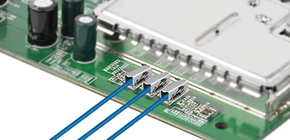
WAGO’s 2065 connectors are consistently applied and used
2065 Series Surface Mount (SMT) PCB terminal blocks from WAGO are designed to connect and reconnect wires consistently every time. They can be integrated into the very same automatic reflow soldering process as other electronic components in the PCB assembly. The automated solder process is optimized once, delivering stable and repetitive results – and perfect solder joints – over and over again.
After they are affixed to the printed circuit board in that automated process, they are ready to accept stripped conductors from AWG 24 to 18. Each connector is designed to accept solid conductors simply by pushing them in, while stranded conductors may be easily inserted using an intuitive operating tool. This same tool can be used for the removal of all wire types. With over 60 years as the leader in spring pressure connection technology, WAGO assures that the installer makes the exact same connection every time. Because there are no variables – there is no possibility of variance. Precision is designed in from the outset.
2. Soldering is hot (and it can get that way quickly)
As was stated before, the amount of heat applied when manually soldering can have a serious negative impact on the integrity of the completed connection if not done with precision every time. Because the composition of solder is often eutectic – meaning that the combination of metals employed melts/freezes at a lower temperature than the individual elements themselves – it is essential that the soldering device is scaled appropriately to match those unique temperatures. In older soldering guns/pens/irons this was done using adjustable bimetallic or magnetic regulation. In more modern equipment, wattage – and hence temperature - is controlled by microprocessors designed to offer more consistent output.
One of the challenges inherent with any soldering tool is that the device is only capable of controlling so much. There is usually a wattage threshold – a set-point – which the tool needs to reach before beginning to cool and initiating the cycle again. This cycle of heating and cooling is exacerbated in practice by unique heat dissipation factors, i.e., the thermal mass of the individual elements being soldered as well as the thermal mass of the soldering tip itself. Larger surface areas in either can dissipate heat more rapidly and thereby result in more extreme fluctuations of temperature as they ramp up to reach the prescribed threshold again.
Added to this variability is the human factor. How the device tip is applied to the element being heated is a practiced, but imperfect art. If the area of contact is small, thermal linkage will also be small. In contrast, if the area of contact is greater this causes heat to transfer much more rapidly. The difference between these two use cases can create a great difference in the consistency of connection. This variance can be further complicated if there are oxides present at the area of contact caused by contaminants resulting in a hindrance of smooth heat application.
Excessive heat, or heat applied too quickly, can thermally stress other proximal components, e.g., very commonly melting conductor insulation creating exposed portions of wire that can become weak points in terms of dielectric protection, bending and flexing stresses, and risk of oxidation.
In any case, variation of temperature has a profound and often negative effect on consistent solder joints. Thankfully again, there is a readily available solution.
The connection of WAGO’s 2065 PCB Terminal Blocks is temperature independent
The automated reflow process is optimized according to the recommended reflow temperature profile and removes all application temperature variability. Then connecting the highly compact (2.7 mm tall) 2065 PCB terminal blocks to flying leads does not require any special temperature considerations at all. Wires are either pushed in directly or inserted easily with the use of a tool as we have stated before. And that is that. Temperature or the inherent challenges thereof have absolutely nothing to do with the reliability of the wire connection process at all.
That being said, because WAGO is the innovator and acknowledged market leader in spring pressure termination technology – highlighted by the industry-changing introduction of the CAGE CLAMP® in 1977, they have decades of expertise in dealing with variable operating temperatures in end-use applications. One of the great advantages of spring pressure technology is that it is impervious to the rigors of temperature cycling in the field. The 2065 is designed with a simple two-piece construction: a stainless steel spring for contact force and tin-plated copper outer shell for carrying current and surface mount fixation to the PCB that has an installed temperature range of -60 °C to +120 °C. If temperatures approaching those extremes were ever actually encountered in the field, chances are pretty high that in practicality the 2065 would be one of the last survivors remaining functional on the board.
3. Cold solder joints are unseen dangers
Cold solder joints are one of the more nefarious of the many possible printed circuit board connection failures. For one, on the surface they look just fine. Their flaws are hidden – virtually indiscernible to the naked eye, but seriously evident in testing or operation. A cold solder joint can be caused in a number of ways, the most common being an uneven distribution of heat during the wetting process that leaves the interior of the solder insufficiently wetted while the exterior appears to be perfectly normal. This frequently happens when a soldering tool is applied to the solder directly instead of to the component lead being soldered. This flaw is even more difficult to detect with RoHs-compliant solders as these solders present a similar external appearance to cold solder joints with leaded solder. While cold solder joints are also possible with reflow soldering of surface mount components, those scenarios tend to be much more controlled and structured by design to minimize this risk.
Cold solder joints can also occur when oxides are not sufficiently removed by the flux involved. There is a time gap between when flux becomes chemical active (and thus eradicating oxides) and the time when solder melts. This time gap needs to be just long enough for the flux to do its work while not being so long as to overheat the solder. The required ramp-up of temperature needed for flux activation and solder liquefaction needs to be carefully harmonized so as not to enable either of these extreme conditions.
An additional cause for cold solder joint failures can be the external introduction of vibration to the PCB before the solder joint has completely cooled. This risk is even greater when soldering a wire directly to a PCB. The chance for movement during this operation is extremely high. Whatever the cause, a cold solder joint can be a frustrating source of failure/damage.
2065 connections are unambiguous
It’s not only that cold solder joints create weak or poor electrical connections to circuit boards that is worrisome; it is that those weak or poor connections are not obvious that gives us pause. It’s one thing having to redo work in the shop, it’s another to have to redo or replace it in the field. This is obviously not the case with the 2065 connector. Once the connection is made, the installer can confidently see that it has been made. Knowing that the contact force will be the same regardless of conditions – even in those vibration situations – installers can walk away knowing that they have made a good connection and that their work is done.
4. Too much solder is suboptimal
It should go without saying that because solder is a conductive material, it really should not spread into contact with other components or pads on the PCB. However, we all know this happens more often than we would like. These solder ‘bridges’ are obvious short circuit hazards that can damage equipment, precipitate system failure and thus should be avoided if at all possible. These bridges can be caused most frequently by excess solder that is not adequately cleaned or cleared from uninvolved contact points.
2065 connections are clean
Not only is it possible, but is downright preferable to use solutions that bypass the need for extensive cleaning altogether. Because 2065 connections are dry connections, there is no possibility of bridging or short-circuits due to the connection.
5. Too little solder is suboptimal
Conversely, a soldered connection that has too little solder applied is an obvious risk for loose or inferior connections. The sheer lack of mass may make the connection less stable, more brittle, and susceptible to breakage and failure. In electronic circuitry, these loose connections are costly and ultimately unnecessary occurrences. It merely takes a minimal amount of vibration or disruption to work loose a weakly soldered connection and create an at-risk situation. For a soldered joint to be fully effective, the solder must surround component leads uniformly on all sides. Any weak spots will present easy egress points through which the wire may fracture and pull free.
2065 connections resist connection weakness
2065 Series SMT PCB terminal blocks are designed to be fully functional throughout the life of an installation. Not only is its dynamic spring resistant to the effects of vibration and thermal cycling but the pull out to failure force of the 2065 exceeds 60N or more – that is more than twice that required by industrial standards for a 20 AWG wire. Moreover, conductors can be inserted, removed and reinserted again with the same results expected each time, and without enduring the risk of connection degradation that solder joints incur when soldered, desoldered and then soldered again.
Further, because the inserted conductor is surrounded on all sides by current carrying elements, there is far-lessened risk of stranded wires splaying when using WAGO’s 2065 Series SMT PCB terminal blocks as compared to other PCB terminal blocks. No ‘weak point’ exists as it does at the abrupt transition between the solid solder and the often highly flexible strands of wire in a solder connection.
Summary
Even though installers have for many years successfully used hand soldering techniques to connect wires to PCB component boards, as our industry moves beyond the age of artisan craftsmanship, WAGO’s 2065 Series Surface Mount PCB terminal blocks offer a risk-mitigating alternative. By eliminating variability in installation, they are easy to use, compact, safe, clean, temperature-cycling resistant, reusable and reliable over the lifetime of the end product. In other words, WAGO’s devotion to quality assures connection integrity – every time.
Text: CORY THIEL, WAGO
Photo: WAGO