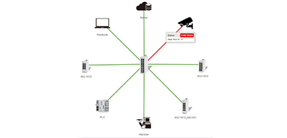

WAGO’s 852-1812 Lean Managed Switch streamlines the process of network management by reducing the number of parameters for quick and easy setup. Enabling the built-in Web Base Management tool gives access to network configuration and commissioning parameters, which allows the user to configure Ring Networks even without having extensive IT knowledge. Web visualization displays a clear visualization of connected devices, port usage, and error diagnostics.
One of the more convenient features of the 852-1812 Lean Managed Switch is how easy it is to use in establishing a robust, available, and secure Redundant Ring Network. It is not possible for device signals to loop from one Ethernet port and return on a different port in a network without first establishing a ring protocol.
Rapid Spanning Tree Protocol (RSTP) is one of several protocols frequently used in factory automation, energy, aerospace and elsewhere according to network segmentation per IEEE802.1Q. By using three 852-1812 Lean Managed Switches from WAGO, and configuring them for the Rapid Spanning Tree Protocol, one can prepare a network for redundant communications.
Part of the architecture is Ethernet Ring Protection Switching (ERPS). Functioning on a principle of ‘loop avoidance’, i.e., creating inherent blocks within the network that preclude potentially dangerous looping of service traffic. Below we demonstrate this ERPS concept and how a trio of WAGO 852-8212 Lean Managed Switches can be effectively utilized.
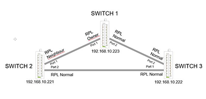
In the ERPS example shown above:
Switch 1 is the Main Switch – with an example IP address of: 192.168.10.223
Switch 2 is the Neighbor to Switch 1 – with an example IP address of: 192.168.10.221
Switch 3 is just default Normal Mode – with an example IP address of: 192.168.10.222
The remainder of the ports on each of the three switches are standard Ethernet ports used for networked devices.
Under normal conditions, data flows through the Normal mode ports to each switch. Switch1 RPL-Owner and Switch2 RPL Neighbor create a block to prevent the connection of a complete network loop. When a failure is detected within the operational Ring network, the Switch that has been affected by the network fault will generate a Signal Fail (SF) message to notify the other switches in the Ring of the failure.
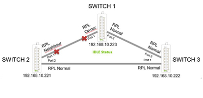
The next alert (shown in the image referencing 'idle status') causes ERPS protection switching to occur and block the afflicted port in order to protect the continued network integrity of VLANs. At the same time, it generates a fault message which is sent because of the signal failure. This message is received at both Switch1 RPL-Owner as well as Switch2 RPL-Neighbor to alert them that there is a fault somewhere in the Ring and to change their operation. This tells Switch1 RPL-Owner and Switch2 RPL-Neighbor to remove their blocks without imminent concern of a network loop. The process makes the ERPS protection switch over to start communicating to devices on the other side of the fault.
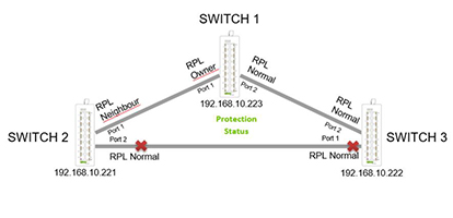
When the failed link has been repaired (image showing 'Protection Status' above) and is again working properly, the previously affected Switch will send a new message to remove the currently blocked ports from the Faulted Switch and to restore Switch1 RPL-Owner and Switch 2 Neighbor back to their prior state of blocking and preventing unwanted looping.
If the 852-1812 Switch needs to be reset to factory default settings, simply press and hold the Reset switch for more than 10Sec and all parameters will be reset (including passwords) as well as setting the IP Address back to the default IP Address: 192.168.1.254
As an added benefit to point-of-failure mitigation, the 852-1812 Switches are designed to also support Redundant Power Supplies. The PWR connection – as seen below – is used for the standard Power Supply and the RPS is for a Redundant Power Supply. When the Redundant Power Supply takes over, the ALM contact will simultaneously close and send an alarm status to the main controller to annunciate the condition.
As can readily be seen, the 852- Lean Managed Switch series has not only reduced parameters for ease of configuration and commissioning but has also abundant features that protect with signal and power redundancy in Redundant Ring topologies.
Text: Tracy Lenz, WAGO
Photo: WAGO