

A growing trend towards Clean Energy implementation - despite the VUCA (volatility, uncertainty, complexity and ambiguity) realities of our tumultuous age continues to march along a strong upward path. Renewables, which were once viewed skeptically in terms of cost, efficiency and overall market acceptance have now established a firm foothold due in part to “rapid technology improvements and decreasing cost of renewable energy resources” as well as because of ongoing concerns regarding climate change stability and sustainable resources.
“It’s going to be a record year for renewable energy development in the U.S. in 2022,” Richard Sansom, head of commodities research at SandP Global Market Intelligence explained,“ with 44 GW of solar 27 GW of wind power set to be installed alongside more than 8 GW of battery storage.” This trend is spurred on by several factors including: continued regional efforts (at a municipal and state level) towards carbon reduction and proposed Federal policies to do the same, as well as by a decline of an estimated 85% LCOE (Levelized Cost of Energy) over the last decade.
Despite this overwhelmingly encouraging outlook, the industry is yet evolving with innovations and best practices changing daily as more systems are being installed in both residential and commercial locales. With that in mind, we shall take a closer look at the many considerations we can take into account when designing components of these systems.
The Solar Pass Through Box and Where it Fits...
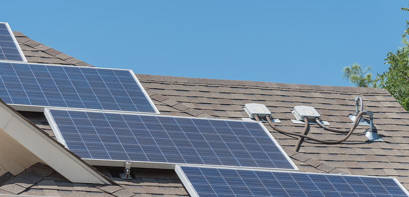
A Solar Pass Through Box serves a purpose precisely as it sounds. It is an enclosure that serves a junction box where various wires from solar panels/ arrays (that are typically mounted in sun-accessible locations outside - for example, on a rooftop for residential installations) - are connected and passed through to the interior of the structure where the collected energy can be distributed to electrical mains, stored or otherwise utilized - for example, through a roof top into an attic in a residential installation. Because they serve as transitions between outside-rated solar photovoltaic (PV) cables to inside-rated traditional wiring, they are also sometimes referred to as ‘transition’ boxes.
While various manufacturers offer pre-configured, even pre-determined pass through solutions, the sheer number of variations and options that are possible allows for a highly customizable range of designer/installer-selected combinations depending upon the unique system requirements of the desired end application. Let us explore therefore some of the more typical component options available to the savvy designer and some of the criteria for those selections.
Enclosure:
The most obvious component of a pass through box is the enclosure itself. Primarily designed to protect the electrical and electronic elements from climatic damage, enclosures are available in a variety of materials from fiberglass and polycarbonate to aluminum, painted, galvanized or stainless steel.
Regardless of its material composition, the box itself typically conforms to one of two NEMA ratings: NEMA 3R or NEMA 4X dependent upon the expected environmental conditions of the location, the sensitivity of the installed components, and of course the criticality of the mission. According to the NEMA 3R standard, this relates to:
Enclosures constructed for either indoor or outdoor use to provide a degree of protection to personnel against access to hazardous parts; to provide a degree of protection of the equipment inside the enclosure against ingress of solid foreign objects (falling dirt); to provide a degree of protection with respect to harmful effects on the equipment due to the ingress of water (rain, sleet, snow); and that will be undamaged by the external formation of ice on the enclosure.
While according to NEMA 4X, this relates to:
Indoor or outdoor use to provide a degree of protection to personnel against access to hazardous parts; to provide a degree of protection of the equipment inside the enclosure against ingress of solid foreign objects (windblown dust); to provide a degree of protection with respect to harmful effects on the equipment due to the ingress of water (rain, sleet, snow, splashing water, and hose directed water); that provides an additional level of protection against corrosion; and that will be undamaged by the external formation of ice on the enclosure.
The major differences between the two standards are readily discernable when observing the comparision between foreign object protection against falling dirt as it states in the NEMA 3R verbiage and windblown dust as it suggests in the NEMA 4X text. It is also evident, we look at water ingress protection against rain, sleet, snow as it reads in the NEMA 3R documentation and rain, sleet, snow, splashing water, and hose directed water that are cited in the NEMA 4X standard more extensively.
It is recommended that regardless of the enclosure type, Solar Pass Through boxes be mounted at approximately a 14” pitch to minimize the potential damage that could be caused by ‘pooling’ water or potential ice dams. Some enclosure (Soladeck, EZ Solar) also have canted tops to assist in further facilitating condensation and moisture run-off. Each manufacturer will have instructions for mechanisms of mounting securely and safely.6
Many residential-type transition boxes have pre-molded seamless flashing to securely aid and seal mounting on asphalt shingled rooftops.
Cable Grips:
Closely related to the enclosure selection process - and often offered/sold in conjunction from the same manufacturer (Cooper Crouse-Hinds bundles this, for example) are Cord Grips, which provide mechanical strain relief for cables entering the enclosure and are ‘skinned over’ when not in use to prevent water or other contaminant ingress. Despite their inherent flexibility and universality, it is nonetheless important to confirm that the Cable Grips selected are appropriate for both the number and size of the cables being utilized.
Cables/Wires:
Generally, there are two main types of wires employed in Solar Pass Through box designs - outdoor or indoor specific - and each is rated thus accordingly. Outdoor- graded wires are those which extend from the solar panels/arrays into the enclosure through the aforementioned Cable Grips. These upstream wires are most likely multi-stranded copper photovoltaic (PV) or underground service entrance (USE)-2 cables and tend to be more exposed to environmental elements. Because of this, PV wire conforms to the UL 4703 PV standard, which...
“...covers single-conductor, insulated and integrally and non-integrally jacketed, sunlight resistant, photovoltaic wire rated 90 °C wet or dry, 600 V, for interconnection wiring of grounded and ungrounded photovoltaic power systems as described in Section 630.31(A) and other applicable parts of the National Electrical Code (NEC), NFPA 70.”
Most PV cables that are utilized in solar installations incorporate single layer XLE (cross-linked polyethylene) insulation with an extra layer of sheathing that has been designed to withstand the myriad rigors of the persistent outdoor climates and extreme temperatures of up to 90 °C.
On the other side - downstream conductors that exit the Solar transition box, (for example through conduit into the attic, structure or into another enclosure or device) are frequently either Thermoplastic High Heat-resistant Nylon (THHN)cables or Thermoplastic Heat and Water-resistant Nylon (THWN-2) cables. The primary difference between the two is the extended maximum temperature rating in wet locations to which the THWN-2 is rated: 90 °C, compared to the THNHN which is rated: 75 °C. The disparate ratings are the result largely of the THWN-2’s PVC being considerably less hygroscopic, i.e., permeable, than that of the THHN thus attaining a higher degree of water resistance.
In practice, modern Thermoplastic-based wiring is dual rated as both THHN/THWN-2 and therefore is resistant to high heat and water in wet or dry locations.
There are two additional elements that need to be considered when selecting proper cables for a Solar Pass Through box: wire gauge (AWG7) and length (feet). Wire gauge is fairly basic in that it must be appropriate to the current being carried throughout the system. That being said, a typical wire gauge range for upstream incoming wires is expected to be 12 through 10 AWG while the downstream output wires are expected to be 12 through 10 AWG. In spite of these intended ranges, most wires are rated between 14 through 4 AWG stranded cooper conducors. As a starting point, 10 AWG cables capable of carrying up to 30 Amps are suitable for most residential and small solar installations.
However, there are many caveats to this somewhat arbitrary rule of thumb. Not the least of these is the previously mentioned length of specified cables. Length of run can dramatically impact voltage drop, which can thereby then deleteriously impact the stability, safety and suitability of the cabling.
To understand and determine the influence that length can have on wiring decision-making, we can use the following formula for calculating the VDI (Voltage Drop Index), which equals:
(Amps x Distance)/(Volts x Percentage of Loss)
An approximately sized wire - with length factored in - can then be determined by rounding up the VDI to the nearest corresponding value in a chart such as the following:
| Voltage Drop Index | Wire Gauge (AWG) | |
| 1 | 16 | |
| 2 | 14 | |
| 3 | 12 | |
| 5 | 10 | |
| 8 | 8 | |
| 12 | 6 | |
| 20 | 4 | |
| 34 | 2 | |
| 49 | 1/0 | |
| 62 | 2/0 | |
| 78 | 3/0 | |
| 99 | 4/0 |
Beyond this, there is yet one further consideration that should be cautioned herein, and that is regarding the inherent variability of temperature that can significantly affect electrical resistance and thus the requisite current being carried particularly through more-exposed upstream-side wires.
In practice, this is most negatively impactful in regions of extreme fluctuations of temperature, which are thankfully atypical for most installations. However, it is good to understand the process for calculating the appropriate correction factor.
First, using NEC Table 690.31(A) a correction factor can be determined based upon whether the conductor being used is rated for 75 °C (THWN) or 90 °C (THHN/THWN - 2/PV Cable). This rating will generate the appropriate correction factor for the wiring as seen below.
| Ambient Temperature | 75 °C Conductor | td>90 °C Conductor | ||
| 26-30 | 1.00 | 1.00 | ||
| 31-35 | 0.94 | 0.96 | ||
| 36-40 | 0.88 | 0.91 | ||
| 41-45 | 0.82 | 0.87 | ||
| 46-50 | 0.75 | 0.82 | ||
| 51-55 | 0.67 | 0.76 | ||
| 56-60 | 0.58 | 0.71 | ||
| 61-70 | 0.33 | 0.58 | ||
| 71-80 | - | 0.41 |
Secondly, multiple current-carrying conductors being routed through a raceway or cable must be derated as well according to NEC Table 310.15(B)(3)(a) as follows:
| Number of Conductors | Derating Factor | |
| 4-6 | 0.80 | |
| 7-9 | 0.70 | |
| 10-20 | 0.50 | |
| 21-30 | 0.45 | |
| 31-40 | 0.40 | |
| 41 and above | 0.35 |
Both factors must then be used to derate the allowable amperage for the conductor.
Rated Amperage/(Correction Factor x Derating Factor)
We can then round up to surmise the next benchmark amperage in our wiring Table in order to select an appropriately specified cable.
Terminal Blocks and Connectors
Now that the enclosure, the cable grips and the wiring have been selected, it is time to explore the connections and the heart of the Solar Pass Through box. As with any electrical componentry, terminal blocks and connectors must adhere to the same standards, codes and best practices as do all other elements within the PV system. It is essential therefore that all connections are specified to meet or exceed relevant voltage, amperage and wire size requiprements.
These solar wire terminations typically fall into two broad but distinct categories: rail mount terminal blocks or wiring splicing connectors.
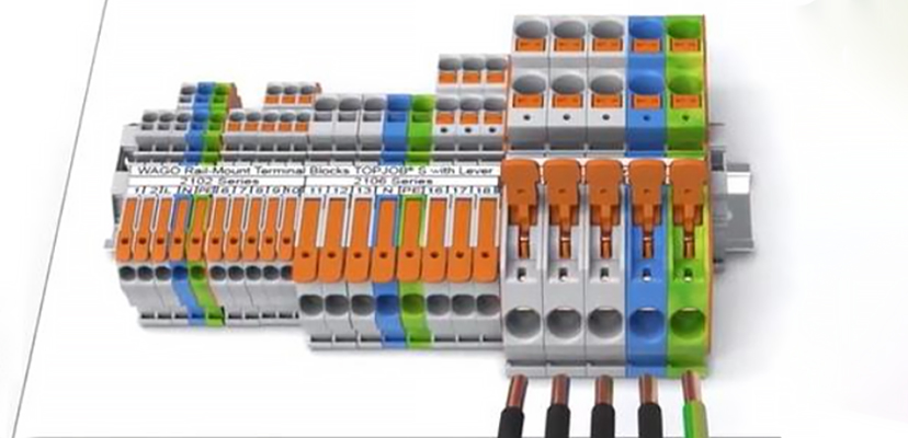
Terminal Blocks: Many Solar Pass Through boxes are shipped with a short piece of DIN 35 rail pre-installed, which invites the use of rail mount terminal blocks and accessories for establishing electrical connections. Some solar enclosure distributors will even pre-package terminal blocks bundles into their various offerings to save on SKU’s for the end customer. Many more, however, will simply leave the terminal block selection process up to the installer’s discretion.
Fortunately, there are many quality options from which to choose. Terminal blocks from manufacturers such as Phoenix Contact, WAGO, Weidmuller, ABB, Wieland and others are designed in a wide variety of styles, sizes, functions. and colors to accomodate a vast customer-centric array of end use operations.
Whatever configuration is thereby ultimately desired, there are several key attributes that can markedly ease installation, peace of mind, and user accessibility that deserve deeper exploration.
Front or Side Entry: One of the more obvious options is choosing between front (top) and side entry terminations. In many OEM application settings, front entry is the strongly preferred choice for design engineers because of its space-savings and easy access. However, in the specific case of PV cables used in solar applications, the rigidity of the insulation sheathing and the typically horizontal entry direction of the upstream wiring coming from the solar arrays give the nod at times to side entry terminal blocks or perhaps terminal blocks that have angled wire entry locations.
A further consideration in this decision-making process may actually be technical. NEC Article 338.24 indicates that the radius of the inner edge of any bend shall not be less than five times the diameter of the wire. Because solar wiring with derating is sometimes larger in diameter in situ, this means that the sharp turns sometimes required by tight spaces may be contrary to Code requirements and therefore not recommended. Furthermore, evidence in fire-inducing solar installation incidents can be traced back to possible cracks in PV cable insulation/ This serves as further discretionary support for the use of side entry terminal blocks.
Furthermore, evidence in fire-inducing solar installations has been traced back to possible disruptions or gaps in PV cable insulation that initiated dangerous electrical arcing. This sobering thought serves as further support for the systemic use of side entry terminal blocks to minimize insulation bending and the subsequent cracking thereof.
Actuation Type: For terminal blocks, there are two main methods for activating and connecting wires, i.e., actuation. In Solar Pass Through boxes, there are: screwtype on the one hand and spring pressure terminations on the other. Both have been used in the most demanding, high visibility installations for over seventy years. Each has innate benefits and challenges for use in Solar PV boxes.
For screw-type terminations, the typical machinations of connection involve inserting an appropriately stripped wire into the designated terminal block opening and then lowering a conductive clamp onto the exposed wire within through the use of repetitively circular motions of a screwdriver which tightens the screw within the clamp down. Unfortunately, there is an inherent variability when using screw-type connections - the proclivity therein is for some installers to under-tighten the screws for fear of damaging the sensitive wires (especially in the case of stranded conductors)while other installers instinctively muscle through and subsequently over-tighten the screws. Either of these cases could severely lessen the electrical integrity of the overall connection and create a potentially catastrophic electrical environment. Therefore, conscientious manufacturers and standards organizations require the use of special torque screwdrivers, which must be carefully calibrated on a regular basis to assure proper torque is maintained and reliable connections are assured. Any laxity in calibration or operation could void manufacturer’s warranties and expose the installation to serious liability concerns.
Unfortunately, diligence in installation is only a portion of the challenges facing screw-type terminations. Over time or through the rigors of cyclical extremes in environmental temperatures or vibration, flexible wires can settle or shift, or equally as damaging, screws could even back-off or loosen completely. The potential of this damage requires constant vigilance at the installation site and an active preventive maintenance schedule of monitoring. assessing and retightening.
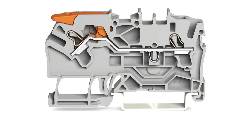
Spring pressure terminations while perhaps not adopted as early within the industry, were designed to mitigate precisely the risks that are inherent with screw-type terminations. The mechanism for connection in the case of spring pressure termination involves using a screwdriver or other actuation tool to pivot open a conductive spring clamp, inserting the appropriately stripped wire into the resultant opening and then removing the tool, thus clamping the wire securely. This simple three-step process assures a universal electrical connection regardless of operator skill or ability (no over- or under- tightening possible) and entirely without further need for calibration or special torque tools. Because of this, spring pressure terminal blocks are often preferred in field locations where stability in operator, environment or conditions may make reproducible, quality connections difficult.
Most high-quality spring pressure clamp manufacturers go one step further in assuring reliable connectivity by surrounding the conductor on four sides. This technique was popularized by WAGO when they introduced their ground-breaking CAGE CLAMP connection technology in the late 1970s. The ‘cage’ assures that wires do not splay and that a constant and stable contact force remains present through which to carry current.
While pivot tool-activation is still the predominant method of actuating spring pressure clamps, three alternative methods have arisen utilizing this revolutionary technology that provide even more flexibility for the installer. These methods include push-in, push-button and/or lever-actuation. Push-in is precisely what it says – instead of using a tool to open the wire entry, solid (and stranded in some cases) wire is directly inserted and pushed into the opening activating the spring. Push-buttons use some tool to depress the button into opening the clamp. Lever-actuated terminations use the fulcrum of the integrated lever to guide open the wire insertion point providing easy access for the stripped conductor. All three of these alternative methods result in precisely the same quality spring pressure connection as does the standard pivot tool-activated means of opening the clamp. Each option offers the end-user the flexibility to choose the methodology that best fits their unique requirements and needs.
Color: For most installers, a small palette of available terminal block colors is more than adequate for each Pass Through box. Terminal block manufacturers (either screw or spring pressure) traditionally have all had more than enough options available for the most popular color requests. Gray is typically appropriate for AC circuits, but some DC circuits use red/black combinations to make identification of positive and negative terminations easy. Green-yellow hued terminal blocks are frequently used for identifying the ground (earth) blocks that common to the DIN 35 carrier rail. These ground terminal blocks are often used in PVbox assemblies to replace traditional screw-down busbar-type grounding options.
Marking/Indication As with any field installed terminal block assembly, clear marking options help ensure appropriate wiring and safety concerns are met. All major terminal block manufacturers have multiple marking options available and some even offer reel-fed printers to facilitate custom marking.
Wire Splicing Connectors:
Rail mount terminal blocks are not the only available termination option for Solar PV Pass Through box installations. Cost-effective wire splicing connectors offer an extremely granular, lower-cost alternative that still fulfills all safety requirements for residential and/or commercial PV boxes.
These connectors can be installed either as free-floating flying lead connections or may even be able to be installed securely within rail mount carriers.
For free-floating connections, many types of splicing connectors are available. From traditional twist-type connectors (pictured to the left) to push-in connectors to lever-actuated connectors – a wide variety of styles is presently available. All are manufactured to produce quality connections when installed correctly and all can meet or exceed standards requirements.
However, there are certain advantages intrinsic to the process of moving beyond familiar styles of connection to newer forms of connectivity. While twist-type connections are certainly well-known to electricians in North America, the connections that are created are by definition opaque – and are thereby shielded from discerning view by the plastic housing itself. Because of this, the integrity of the connection cannot be visibly confirmed. Additionally, with no test-points integrated into the design of the plastic moldings, there is also no technical way of assuring connection either.
To compound these challenges further, in order to assure the long-lasting integrity of the unseen connection, twist type connectors are recommended to be wrapped with electrical tape to increasingly secure the connection. This is yet another vision-occluded, time-consumptive element to the manual installation process.
To remedy the lack of visibility, many new connectors are molded from transparent plastic that clearly reveals that the electrical connection has been made securely and safely. Beyond this, because the connective mechanism uses the same dynamic spring pressure connection technology as spring pressure terminal blocks and retains the strong pullout capabilities thereof, they do not bear the risk of wires working loose and thus necessitating an additional step of affixing electrical tape to secure them. Test ports are designed into the molding to further assure electrical reliability.
These innovative spring pressure alternates to twist-type connectors most often come in one of two variants: Push-in (also called Poke-in or Stab-in) or lever-actuated. The Push-in variety uses the rigid characteristics of solid – or in some cases, stranded – wire to press open the wire entry point for ease of insertion. The resultant connection meets or exceeds industrial pull-out, vibration and temperature cycling requirements. The only perceived drawback with this type of connector with stranded wire is that if reconnection is necessary (an infrequent occurrence in the field) the wire must be cut, and a new connector used in its stead. This consequence is not necessary for solid wire installations in push-in connectors as the conductor can be purposefully twisted free, restripped and reinserted.
For lever-actuated splicing connectors, this is an entirely non-existent concern as the lever is designed to be opened and closed repeatedly before experiencing any subsequent degradation of contact. In the realm of field operation, the ease of use offered by the binary open-close functionality of the clamping device is reassuring as is the transparent housing which gives visual indication of a secure connection. Most connectors of this type will need to be rated for at least 10 amps depending, of course, upon the specific requirements of the end use PV application.
Special Functions:
In some cases, installers will require additional functions to be actioned within a Solar Pass Through box. These ancillary functions are typically specified to enhance safety of resources or personnel and tend to fall into the allied but distinct categories of fusing or overcurrent (OC) protection. In some cases, these additions are optional, but in others they are required by code or configuration considerations.
Fused Disconnects (Optional)
Typically, solar panels utilize 10 AWG wires that are able to safely carry up to 30 A each. This may be sufficient without any additional fusing if the associated panels are connected in series because – in that particular instance – there would be no increase in current flow in the event of a disruption. However, this is not the case if the panels are connected in parallel as the resultant overcurrent would be cumulative and exceed the normative capabilities of the individual wires and thus could cause dangerous overheating situations conducive to ignition and system damage.
Therefore, many Solar PV Pass Through Boxes are fitted with finger-safe fuse-holders or circuit breakers. When choosing overcurrent protection, several concepts should be taken into consideration to conform with NEC recommendations. The initial calculation begins with identifying the short circuit current Isc. (The short circuit current is defined as being the current through the circuit when short circuited, i.e., when voltage equals zero.)
Multiplying the Isc by 1.25 (giving a 25% head room) generates IMAX, or the maximum allowable current for the circuit. In non-continuous current situations this may be sufficient, but in PV applications current is considered continuous and thus a second calculation needs to be made to provide an additional 25% of head room to forestall nuisance tripping and provide adequate protection. In these cases, the calculation would be IMAX x 1.25 to generate the overall circuit ampacity.
In practice, this two-step approach can be combined into one simple calculation wherein the iterative 25% cushions are neatly combined: 1.25 x 1.25 = 1.5625. Thus, the circuit ampacity can be calculated as: 1.5625 x Isc
The result of this calculation is an amperage, which will help guide the selection of appropriate fusing at or just above the calculated value. Since fuses are sold in standard sizes of 6, 8, 10, 15, 20, 25, etc. there should be fuse in range that makes sense. A further word of caution, however, is in order, especially for commercial/industrial installations. That is that most fused devices are rated for 40 °C, which is fine for residential use – but perhaps not so for some potentially high heat environments. In those cases, manufacturer deratings should be given strong consideration.
Surge Protection (Optional)
Normally when we think of Surge Protection, lightning and its catastrophic results come immediately to mind. This is one type of surge of course but is somewhat incomplete when examining the many different types of transient voltages that might negatively impact a Solar Pass Through Box and the sensitive electrical equipment within. Any manner of sudden release of energy – arcing, capacitor discharge, genset swells, or yes, even lightning – can cause damage, downtime or disaster. To counteract the risks these transient voltages may impart, installers can use appropriately sized surge protection devices (SPDs) to help protect the integrity of the installation.
Unfortunately, “Photovoltaic systems are inherently exposed to direct and indirect lightning effects. For high capacity systems, the deployment of solar cell arrays requires a large area with commensurate exposure to direct lightning strikes at the local annual rate of ground strikes per unit area. The presence of a ground grid related to the PV system in an otherwise isolated area may act as a collector of lightning ground-current from nearby strikes.” By their very nature, solar panel arrays are climactically exposed, hence requiring the intervention of surge protection devices.
Typically, DIN rail mount SPDs come with one of three distinct types of active componentry integrated within: gas arrestors, suppressor diodes, or metal oxide varistors (MOVs). For surge protection in solar applications, it is this third type – the metal oxide varistor – that is most commonly used. MOVs as a group are generally considered to have a 5-25ns response time and are designed to an ANSI and IEEE accepted 8/20μs waveform that is representative of indirect lightning strikes.
For our purposes, these SPDs would be classified as Type 2 according to UL 1449 [2].
Type 2: Permanently connected SPDs intended for installation on the load side of the service equipment overcurrent device; including SPDs located at the branch panel and molded cases SPDs.
To be effective, the voltage level of the SPD should be lower (20% lower is recommended) of the system’s overall withstand rating. In this way, operational voltage could be maintained without complete isolation of the trigger event while minimizing the negative effects of the overvoltage situation.
Summary:
While the role of a Solar PV Pass Through Box in a solar energy system is somewhat understated, it yet retains many subtle complexities of nuance in the selection of its component parts. While best practices and selection guides are available and we have spoken of many herein, each installation should be considered as unique and reflect the myriad options and variants available to the informed designer.
A few of the processes for selection are challenging, and some even require math. However, studies have indicated that the number of global renewable installations will continue to rise in the coming decades so the proliferation of panels - and hence Solar Pass Through Boxes - shall continue to rise commensurately.
Text: JOHN KENWORTHY, WAGO